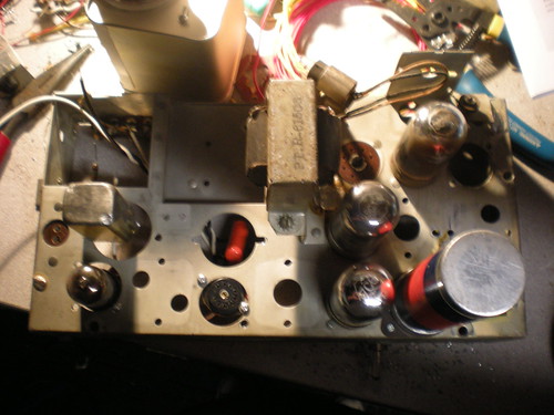
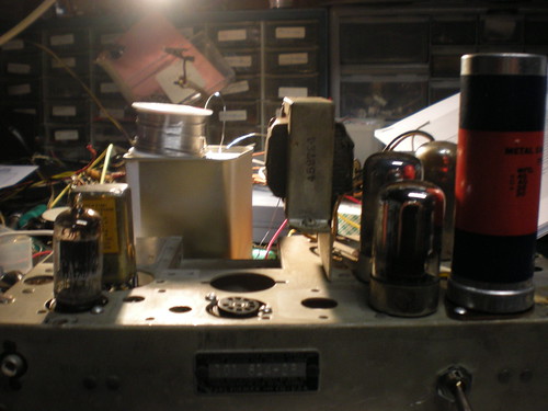
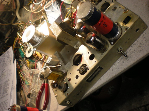
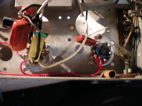
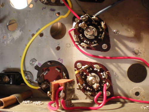
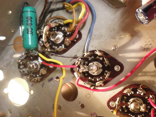
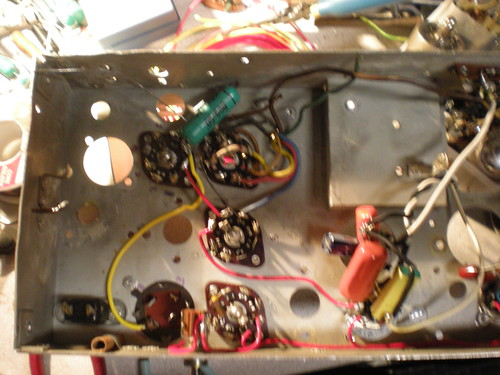
New Tube Amp. Need to still replace the filter cap but its working just fine for the time being! 3 12AX7 only 2 being utilized 6AQ5A Output and a 6X4 rectifier.
Latest Bench Shot
Showing posts with label DIY. Show all posts
Showing posts with label DIY. Show all posts
Monday, March 14, 2011
Wednesday, February 16, 2011
Silvertone+Altech=Silvertech
Labels:
Altec,
DIY,
Silvertone
Thursday, February 10, 2011
Theremin midi board is like using autotune
Via Hack A Day [Steve Hobley] built a Theremin interface board that tracks pitch and volume.

Using this setup he’s able to pass data over a midi interface which effectively converts the instrument into a non-contact midi controller. As we joked in the headline, this does allow for the use of autotune, by snapping notes that are sharp or flat to the center of the nearest pitch. But you should watch the video after the break to see [Steve] show off the other features as well. A keyboard can be used to seed a starting pitch, with arpeggios of several different tonalities built on top of it based on the input from the Theremin.

Using this setup he’s able to pass data over a midi interface which effectively converts the instrument into a non-contact midi controller. As we joked in the headline, this does allow for the use of autotune, by snapping notes that are sharp or flat to the center of the nearest pitch. But you should watch the video after the break to see [Steve] show off the other features as well. A keyboard can be used to seed a starting pitch, with arpeggios of several different tonalities built on top of it based on the input from the Theremin.
Want the details? Unfortunately you’ll have to pay for the schematics. But the concept is still just as interesting to read about, even if you don’t know what went into the system.
Labels:
DIY
Monday, January 17, 2011
Altec 1566A
Tomorrow I am going to start building an Altec 1566A. I got the schematic form here. I scored input and output transformers at APEX today hope they are the right values. They are made by Tetrad Co. Inc.
Input is a LEAR#91881 T 102
Output is a LEAR#91934 T 106
If anyone has anymore information on these transformers that would be great!
Ill keep the blog updated on progress. Also anyone want to start a Hacker/Maker space in Huntington Beach with me?
Input is a LEAR#91881 T 102
Output is a LEAR#91934 T 106
If anyone has anymore information on these transformers that would be great!
Ill keep the blog updated on progress. Also anyone want to start a Hacker/Maker space in Huntington Beach with me?
Labels:
Altec,
DIY,
Personal Build
Friday, January 14, 2011
Tube Powered Flash-drive
I came across an image of a vacuum tube with a flash drive sticking out of it tonight and I thought to my self well my flash drive is stupid looking in its plastic black case so here it is. After breaking it out of its black case I realized that the flash drive its self is really small and would fit right over the pins of the tube so its just wedged onto the pins. Works great!
Labels:
DIY,
Flash-Drive,
Personal Build,
Vacuum Tube
Monday, January 3, 2011
Reboxing
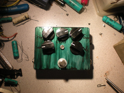
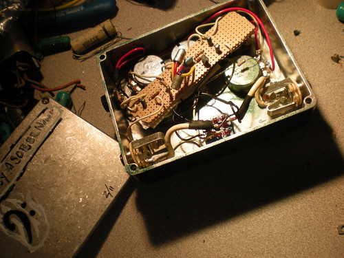
I built this pedal originally about a year or so ago now its two Zvex SHO in series with an in and out loop for each stage and well as volume control for each stage. When I orginally built this pedal I was off in some of my measurments so the loop functionality did not work do to the output jacks touching together. I wanted to try fix this problem as well as try out Frequency Central Layout that adds an additional 2N5457 into the circuit which gives an extra crunchy tone. While cleaning out some of my parts I found this extra enclosure that I had so I figured that now was the time to try it out. Still working on it currently but here are some pictures.
Laying out the box for parts:
Laying out the box for parts:
Adding pots and switches to make sure everything fits and allow for easier soldering:
New circuit form Frequency Cental at the top in the center:
Power jack wired up ready to test out:
Labels:
Clone,
DIY,
Personal Build,
SHO
Sunday, December 12, 2010
This is just freaking cool; From Hack A Day
Link
[Enigma-penguin] built a tablet computer out of a Core2Duo Macbook circa 2007. The battery exploded, damaging the case and a few components inside. But there was hope for a new life as a tablet computer. He removed the screen and tested to make sure the computer would still function without it by using the video out port.
Putting the whole thing back together as a tablet proved to have some headaches. He worked through problems caused by the addition of a touchscreen between the LCD and the bezel and made the connections work with the screen flipped. The finished product looks so good because the bezel has not been turned around like on other tablet builds. Instead, a viewing window was cut in what would have been the case behind the screen.
There’s a little more to be done yet. The black USB cable seen above is the connector for the touchscreen which he plans to internalize. The magnetic sleep sensor has been relocated to the headphone jack. Inserting a plug (no cord necessary) puts it to sleep for transport. There’s also an on screen keyboard and the ability to change the screen orientation from landscape to portrait. After the break we’ve embedded one of [Enigma-penguin's] demonstrations.
Link
Labels:
DIY
Saturday, December 11, 2010
Point Contact PNP
This is from Tube Time Its a point contact PNP Transistor made form a diode.
"My friend Jeri Ellsworth recently figured out how to make a point contact transistor by cracking open a germanium diode. It looked pretty straightforward so (deviating from this blog’s usual content) I took a crack at it myself:"

"The original diode contact serves as the emitter connection. The base is the chip of germanium that is visible in the bottom part of the diode (with the stripe). The collector is a piece of phosphor bronze wire I pulled off the end of a guitar string. I sharpened it to a point with a Dremel sanding wheel and soldered it to a piece of bare wire to make it easier to handle.
The fine-pitched screws are used to maneuver the wires into contact with the block of germanium.
The germanium base is actually n-doped. To create the collector junction, you have to create p-doped regions. One crude way to do this is to apply a burst of current across the reverse-biased junction (positive voltage to base, negative voltage to collector). I don’t know if the mechanism is thermal or electrical, but phosphorus from the phosphor bronze wire gets carried into the germanium, creating the p-type region. For this experiment I used about 200V on a 10uF capacitor, and I discharged it into the junction through a 1K resistor. Jeri originally used something like 20V but I read in a paper several hundred volts were usually used for this purpose.
Jeri used an oscillator circuit to test her transistor, but I got lazy and just put it in a simple inverting amplifier circuit. At first the transistor didn’t work (output was in phase with the input) but after some tweaking of the wires, the output finally went 180 degrees out of phase. This is an absolutely terrible transistor, and the gain is really too low to consider this a transistor."
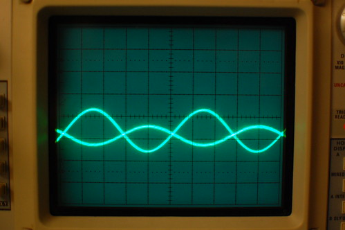
Check out the site for more cool stuff!
"My friend Jeri Ellsworth recently figured out how to make a point contact transistor by cracking open a germanium diode. It looked pretty straightforward so (deviating from this blog’s usual content) I took a crack at it myself:"

"The original diode contact serves as the emitter connection. The base is the chip of germanium that is visible in the bottom part of the diode (with the stripe). The collector is a piece of phosphor bronze wire I pulled off the end of a guitar string. I sharpened it to a point with a Dremel sanding wheel and soldered it to a piece of bare wire to make it easier to handle.
The fine-pitched screws are used to maneuver the wires into contact with the block of germanium.
The germanium base is actually n-doped. To create the collector junction, you have to create p-doped regions. One crude way to do this is to apply a burst of current across the reverse-biased junction (positive voltage to base, negative voltage to collector). I don’t know if the mechanism is thermal or electrical, but phosphorus from the phosphor bronze wire gets carried into the germanium, creating the p-type region. For this experiment I used about 200V on a 10uF capacitor, and I discharged it into the junction through a 1K resistor. Jeri originally used something like 20V but I read in a paper several hundred volts were usually used for this purpose.
Jeri used an oscillator circuit to test her transistor, but I got lazy and just put it in a simple inverting amplifier circuit. At first the transistor didn’t work (output was in phase with the input) but after some tweaking of the wires, the output finally went 180 degrees out of phase. This is an absolutely terrible transistor, and the gain is really too low to consider this a transistor."

Check out the site for more cool stuff!
Thursday, December 2, 2010
Big Muff Triangle
This is a EHX Big Muff Triangle that I have been working on today; Its based on the layout by IvIark
Labels:
Big Muff,
DIY,
Effects,
EHX,
Personal Build
Wednesday, December 1, 2010
T.L.B.
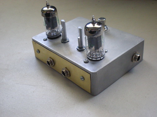
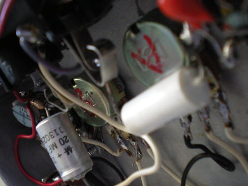
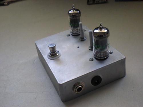
Just another update of the Tube Loop Boost; Its all wired up and works properly but not perfectly, Ill need to do some tweaking to get it working 100%. Well enough chit chat here are some pictures.


Labels:
DIY,
Effects,
Flicker,
Personal Build
Sunday, November 28, 2010
Tube Boost Looper
This is for a project that I am currently working on right now. Its a dual tube boost with a FX loop. Its based on the Bass Paralooper and the Valve Caster . I have two identical boosts, modified with larger input capacitors; Currently I am just using the trim pot to set the gain. More to come later!
Update:
So I drilled out the case yesterday but screwed up on the placement of the jacks for the loop send and return, they are in the way for the tube sockets. I think I'll take a brass strip and use that to cover up the existing hole and mount the jacks to that. Other than that screw up this is one of my most accurate drillings for an fx box.

Labels:
DIY,
Personal Build
Tuesday, November 23, 2010
Mammoth 2
This is yet another attempt at the Mammoth Fuzz I could not get the other to sound like I wanted it to so this one will work hopefully. Same layout as before from Tag Board Effects Used a Dermal tool to grind the Copper away leaving nice pads to solder onto. Build time was about an hour and half.

Please leave a comment telling me what you think.

Please leave a comment telling me what you think.
Labels:
Clone,
DIY,
Effects,
Mammoth,
Personal Build
Monday, November 22, 2010
Spoon Organ
This is from: C i b o M a h t o . c o m
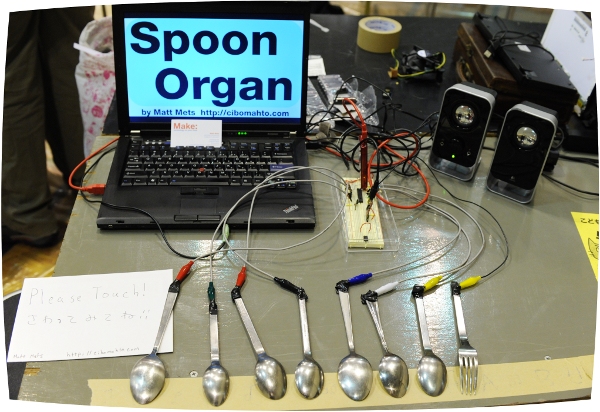
"Spoon Organ is an instrument that I created to show at the Make Tokyo Meeting 06 this past weekend. The user can play musical tunes simply by touching a row of spoons sitting on a table, with a fork added in for good measure. A microcontroller is used to detect changes in capacitance caused by a finger pressing against the metal, which are then sent to a computer using the MIDI protocol."

"Spoon Organ is an instrument that I created to show at the Make Tokyo Meeting 06 this past weekend. The user can play musical tunes simply by touching a row of spoons sitting on a table, with a fork added in for good measure. A microcontroller is used to detect changes in capacitance caused by a finger pressing against the metal, which are then sent to a computer using the MIDI protocol."
Friday, November 19, 2010
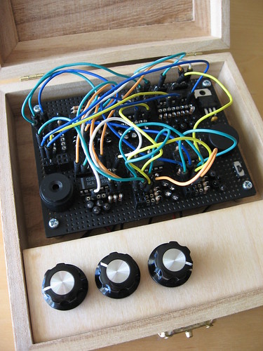
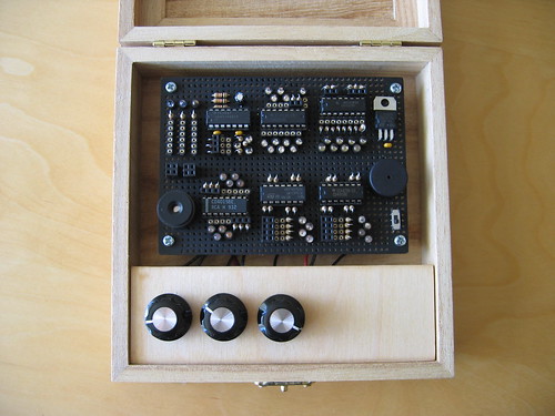
Mini Lunetta Patched Close up
Check out the Electro-music forums for more project info and users' builds.
This one is built bysndbyte's
Monday, November 15, 2010
TorrentMeter - A Steampunk Bandwidth Meter
This is from Skytee
Its and analog gauge that displays the bandwidth of torrents being downloaded.
I got inspired by reading Tom Igoe's article in Make Magazine issue 11, about an antique gauge displaying air quality data from the web. It hit a nerve: friends and I had once built asteam powered teletype. Since we've got fiber optical intertubes at home, I wanted a big brass gauge telling me how big my pipe was. And that's the idea of my TorrentMeter.

Video of it in action.
Full Article
Its and analog gauge that displays the bandwidth of torrents being downloaded.
I got inspired by reading Tom Igoe's article in Make Magazine issue 11, about an antique gauge displaying air quality data from the web. It hit a nerve: friends and I had once built asteam powered teletype. Since we've got fiber optical intertubes at home, I wanted a big brass gauge telling me how big my pipe was. And that's the idea of my TorrentMeter.

Video of it in action.
Full Article
Sunday, November 14, 2010
DIY RAM Memory- Register Style
This is from Instructables.com. Its an amazing hand built three bit memory. 

DIY RAM Memory- Register Style
**UPDATE** I also made a CMOS version here: http://www.instructables.com/id/DIY-CMOS-RAM-Memory/
If you have ever looked at a microcontroller's datasheet, you have probably seen something about registers. Registers are little one or two byte memory storage units in microcontrollers. The register in this instructable can hold 3 bits of data (b/c I ran out of room on my breadboards) using transistors. I did this to prove that I can, however, its not practical as an 8 bit register requires 64 transistors, about 64 resistors and lots of space.
The register is a neat device. It can recieve data when the enable input is, in my circuit, low and it can then latch and save the data even it the data line is changing. My circuit is not the conventional D-type latch because it used more transistors than I had.
Swishercutter left a great comment:
Labels:
DIY
Thursday, October 14, 2010
A sick ring modulator
Just came across this cool ring modulator by zebranalogiczetangas | September 24, 2010
"Experimenting with the ring modulator.
I ´m using the next wave form square, sawtooth, sine.
I´m playing with a guitar modified using singles coil and a amplifier hand made."
I ´m using the next wave form square, sawtooth, sine.
I´m playing with a guitar modified using singles coil and a amplifier hand made."
I really need to build one myself its one of those pedals that i have always wanted.
Sunday, October 10, 2010
Fuzzy Factory Black and White
I forgot that i did a good job on wiring this one thought that I would share.
Monday, October 4, 2010
Subscribe to:
Posts (Atom)


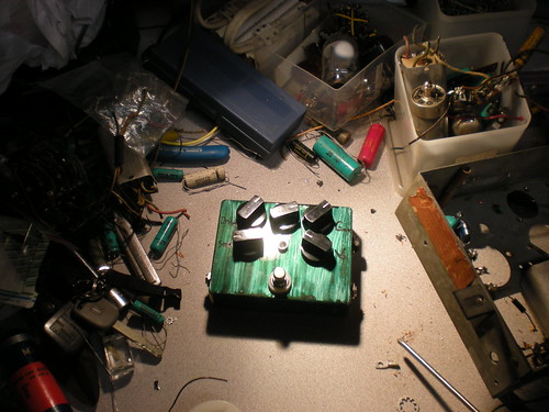
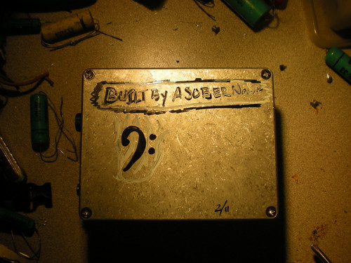


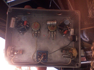


Whenever I see people build large scale versions of commonly available circuits I always think of my electronics instructor...he wanted to build a "Macroprocessor" which would be built from tubes and relays (he is an ex radar tech) as he put it "...it would be as big as a building, would put off a ton of heat as well as making the most wonderful clicking sound as it ran...".
Lets keep going on these types of Instructables...if we forget how these circuits are designed internally we become not only dependent on the circuit always being there but we also risk losing the spark of ingenuity which led to the design in the first place...you can only go further if you know how we got here.
Maybe we can start a "macroelectronics" tag just for things like this.